

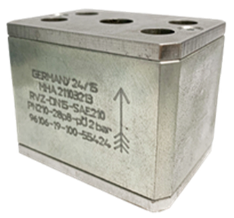
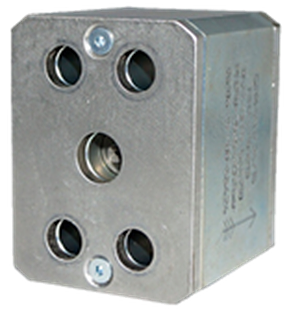
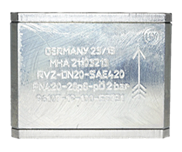
Flange-mounted check valves for lines already on SAE porting: bolted straight to the flange face, so there is no thread in the flow path. The standard cracking pressure is 2 bar — stronger than the threaded types, because this valve is more often holding a load.
State flange class (210 or 420), size, material and seal option — quotes within 2 working hours.
| Type | MHA RVZ-SAE — spring-loaded poppet |
|---|---|
| Classes | ISO 6162-1 (210 bar) · ISO 6162-2 (420 bar) |
| Range | DN15–DN50 — 1/2″ to 2″ |
| Cracking | 2 bar (0.2 MPa) standard — ±30% tolerance |
| Body & poppet | Steel (28p8) or SS316 (44p8) |
| Seat | Polyurethane |
| O-rings | FPM (Viton) |
| Temperature | −20…+100 °C |
Dimension, bolt-centre, weight and MHA order-number tables per class are on this page, as printed in the catalogue.
| At a glance | Code 61 | Code 62 |
|---|---|---|
| Standard | ISO 6162-1 | ISO 6162-2 |
| Pressure | 210 bar | 420 bar |
| Bore at DN50 | 37 mm | 37 mm |
| Bolt hole DN50 | 13 mm | 22 mm |
| Parameter | ISO 6162-1 (SAE210) | ISO 6162-2 (SAE420) |
|---|---|---|
| Rating | 21 MPa / 3000 psi | 42 MPa / 6000 psi |
| Also called | SAE Code 61 | SAE Code 62 |
| Bolt centres at DN15 | 17.5 × 38.1 mm | 18.2 × 40.5 mm |
| Bolt centres at DN50 | 42.9 × 77.8 mm | 44.5 × 96.8 mm |
| Bolt hole at DN50 | 13 mm | 22 mm |
| Body width at DN50 | 100 mm | 115 mm |
⚠ The two do not interchange — the bolt spacing differs at the same nominal size, and the gap widens with size: a few millimetres at DN15, but at DN50 the long side is 77.8 against 96.8 mm. The Code 62 body is also wider (115 against 100 mm) — check the space, not just the pattern.
| DN | Inch | Bore LW | L (mm) | B (mm) | H (mm) | Bolt centres a×b | Hole d | MHA order no. |
|---|---|---|---|---|---|---|---|---|
| DN15 | 1/2″ | 11 | 46 | 45 | 60 | 17.5 × 38.1 | 9 | 55424 |
| DN20 | 3/4″ | 14.5 | 54 | 55 | 70 | 22.3 × 47.6 | 11 | 55425 |
| DN25 | 1″ | 17 | 61 | 70 | 80 | 26.2 × 52.4 | 11 | 55394 |
| DN32 | 1¼″ | 22 | 82 | 80 | 80 | 30.2 × 58.7 | 11 | 55395 |
| DN40 | 1½″ | 28 | 89 | 90 | 95 | 35.7 × 69.9 | 13 | 54350 |
| DN50 | 2″ | 37 | 105 | 100 | 110 | 42.9 × 77.8 | 13 | 55426 |
| DN | Inch | Bore LW | L (mm) | B (mm) | H (mm) | Bolt centres a×b | Hole d | MHA order no. |
|---|---|---|---|---|---|---|---|---|
| DN15 | 1/2″ | 11 | 46 | 50 | 60 | 18.2 × 40.5 | 9 | 55732 |
| DN20 | 3/4″ | 14.5 | 54 | 60 | 70 | 23.8 × 50.8 | 11 | 55731 |
| DN25 | 1″ | 17 | 61 | 70 | 80 | 27.8 × 57.2 | 13 | 55721 |
| DN32 | 1¼″ | 22 | 84 | 80 | 95 | 31.8 × 66.6 | 13 | 55716 |
| DN40 | 1½″ | 28 | 91 | 95 | 115 | 36.5 × 79.3 | 17 | 55022 |
| DN50 | 2″ | 37 | 109 | 115 | 135 | 44.5 × 96.8 | 22 | 55726 |
Compare the Bore LW column in both tables: 11 · 14.5 · 17 · 22 · 28 · 37 mm — identical. Going from 210 to 420 does not add flow; what you buy is pressure capability. What changes is the bolting, and the width and height of the body.
Indicative unit weights
| Size | Weight (kg) |
|---|---|
| DN15 | 1.10 |
| DN20 | 1.50 |
| DN25 | 2.30 |
| DN32 | 3.45 |
| DN40 | 4.85 |
| DN50 | 7.80 |
| Component | Code 28p8 (steel) | Code 44p8 (stainless) |
|---|---|---|
| Body | Steel | SS316 stainless |
| Poppet | Steel | Stainless |
| Seat | Polyurethane | Polyurethane |
| O-rings | FPM (Viton) | FPM (Viton) |
| Temperature | −20…+100 °C | −20…+100 °C |
Stainless costs no pressure here. The limit is the flange class, not the body metal — so 210 is 210 bar and 420 is 420 bar in either material. That is different from the threaded check valves, where stainless drops to 350 bar.
| Included | Not included |
|---|---|
| 1 check valve 2 O-rings 2 holding plates | Adapter plate (separate part number) Flange halves Bolts and washers |
Adapter plates — ISO 6162-1 (21 MPa)
| DN | Inch | Thickness L (mm) | MHA order no. |
|---|---|---|---|
| DN15 | 1/2″ | On request | — |
| DN20 | 3/4″ | 29 | 55443 |
| DN25 | 1″ | 29 | 55444 |
| DN32 | 1¼″ | 33 | 55445 |
| DN40 | 1½″ | 33 | 55446 |
| DN50 | 2″ | 33 | 55447 |
The adapter plate is a flanged steel spacer that lets the check valve be stacked in an assembly — so another component can be removed without taking the check valve out. If you order the valve alone, make sure the flange halves and bolts are already on site.
| Option | Sealing | Use when |
|---|---|---|
| A | No seals | Both mating parts already carry O-ring grooves |
| B | Inlet sealed | The upstream part has a flat face, no groove |
| C | Outlet sealed | The downstream part has a flat face, no groove |
| D | Both sides sealed | Valve between two flat faces — the typical case |
| E | Threaded holes | You need to bolt into the valve body — on request |
This is the most commonly mis-ordered detail. The seal option is set by what bolts to the valve, not by its size or class. If you are unsure, send a photo of both mating faces on WhatsApp — we will work out the option.
| Method | Standard | What it proves |
|---|---|---|
| P10 | DIN EN 12266-1 | Body strength at 1.5× rated pressure |
| P11 | DIN EN 12266-1 | Body & joint tightness (air/hydrostatic) |
| P12 | DIN EN 12266-1 | Seat tightness at 1.1× rated pressure |
Heat numbers appear in the test report — so the batch stays traceable. Ask for the report with the order, not afterwards, while the batch is still identifiable.
210 or 420 — measure the bolt spacing, not the bore (the bore is identical).
O-ring placement has to match the mating faces: A, B, C or D.
Marked by a large arrow on the body. Fitted the wrong way round it blocks the line.
Clean both flange faces first, then tighten the bolts across the diagonal to the flange maker's torque.
Vertical or horizontal both work — the spring is independent of gravity. And controlled reverse flow can be arranged with an orifice drilled through the poppet, but it must be specified with the order; it cannot be done afterwards.
Full dimensions, seal options and part numbers are in the catalogue, as printed; stock and price are not — send the list and we confirm both.
Holding a cylinder in position — the reason the cracking pressure is 2 bar, not 0.5.
Bolted straight onto SAE porting without reworking the block.
Stopping reverse flow back through a pump when the system stops.
With an adapter plate — another component comes off without removing the check valve.
Both are SAE flange patterns: ISO 6162-1 = the 21 MPa (3000 psi) interface, also called SAE Code 61; ISO 6162-2 = the 42 MPa (6000 psi) interface, or Code 62. The bolt spacing differs at the same nominal size — at DN50, 42.9×77.8 mm against 44.5×96.8 mm — so the two do not interchange.
One check valve, two O-rings and two holding plates. The adapter plate is NOT included — that is a separate part number. Neither are the flange halves, bolts and washers.
A flanged steel spacer that lets you stack the check valve in an assembly, so another component can be removed without taking the check valve out. Thickness 29 mm at DN20–DN25 and 33 mm from DN32 up; DN15 on request.
Flow is B to A, marked by a large arrow on the body. Fitted the wrong way round it blocks the line. Vertical or horizontal both work — the spring is independent of gravity.
The standard is 0.2 MPa, which is 2 bar, with a spring tolerance of ±30%. Other opening pressures are available to order.
Because they are usually doing different jobs. A threaded RV is often just stopping backflow, while the flange-mounted RVZ is more often holding a load — and holding a load needs a stronger spring.
It depends what you are bolting to. Four versions: A without seals (both mating parts carry their own grooves), B inlet sealed, C outlet sealed, D both sides sealed — the last being the usual case. Option E with threaded holes is available on request.
Yes — an orifice can be drilled through the poppet for deliberate restricted back flow. But it must be specified with the order; it cannot be done afterwards.
No. Here the limit is the flange class rather than the body metal, so 210 is 210 bar and 420 is 420 bar in either material. Different from the threaded check valves, where stainless drops to 350 bar.
Body and poppet in steel (code 28p8) or stainless SS316 (code 44p8), a polyurethane seat, and FPM (Viton) O-rings. Temperature −20 to +100 °C on both codes.
No. The bore is identical in both classes — 11 mm at DN15 to 37 mm at DN50. Moving up a class buys pressure capability, not flow.
Read the flat of the body: the type, bore and class, then the rating, material code and cracking pressure. The works order number ends in the MHA catalogue number. Send a photo on WhatsApp.
MHA batch tests to DIN EN 12266-1 using P10 (body strength at 1.5× rated pressure), P11 (body and joint tightness) and P12 (seat tightness at 1.1× rated pressure). Heat numbers appear in the test report.
It usually does not need to be. The commonest cause is debris trapped on the seat — flush and inspect rather than condemn it. If it is genuinely damaged, replacement is the practical answer.
DN15–DN25 is our running stock, held in our regional warehouses in Singapore and Malaysia, out within 24 hours of your PO. Larger sizes and stainless builds are quoted with a lead time; quotes within 2 working hours.
Related: threaded high pressure check valves · SAE flange end ball valves · SAE flanges · about the MHA Zentgraf brand · all high pressure valves · baca halaman ini dalam Bahasa Indonesia
