A solid cast one-piece ball valve for isolation duty: fitted once and left there. No body joint means no leak path through the middle — and the consequence is that this valve cannot be taken apart: when the seals wear, it is replaced.
State size, BSPP or NPT, and the working pressure and temperature — quotes within 2 working hours.
| Construction | Solid one-piece casting — not serviceable |
|---|---|
| Range | 1/4″ to 4″ (11 sizes) |
| Bore | Reduced bore — always |
| Pressure | 1,000 PSI / 63 bar (cold rating) |
| Temperature | −29…150 °C — set by the PTFE seat |
| Body | SS316 / CF8M |
| Ends | Threaded BSPP or NPT |
| Operation | Quarter turn, manual lever |
The eleven-size dimension table with part numbers, the 13-item bill of materials and the derating curve are on this page, as printed in the catalogue.
One casting. No body joint. No way in.
A one-piece low pressure ball valve has its body and end connections made from a single piece of material. That one detail drives everything else about it. Because there is no seam between two halves of the body, the solid cast body significantly decreases the risk of leakage — there is simply no body joint to weep from. It is the tightest of the three constructions.
The trade-off is access. The valve trim and seals are inserted through one of the end connections during manufacture, and that is the only route in. It follows that the port size cannot equal the line size — valves of this design are always reduced bore. It also means the valve cannot be taken apart: when the seat eventually wears, you replace the valve rather than re-seat it.
One casting, so the only sealing points are the two threads you make up and the stem. That is the reason to specify it.
At 1/2″ the bore is 9 mm against a 15 mm pipe — roughly 36% of the flow area. If that matters, you need the two-piece.
Specify it where nobody will ever open the valve. If seat replacement is foreseeable, the two-piece; if it has to happen without stopping the line, the three-piece.
75 24 11 to 75 24 18 across 1/4″ to 2″ in BSPP, so it can be ordered against a marine code rather than a supplier part number.
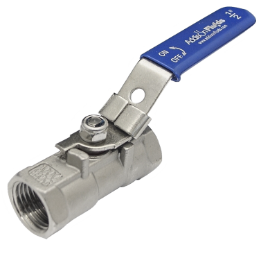
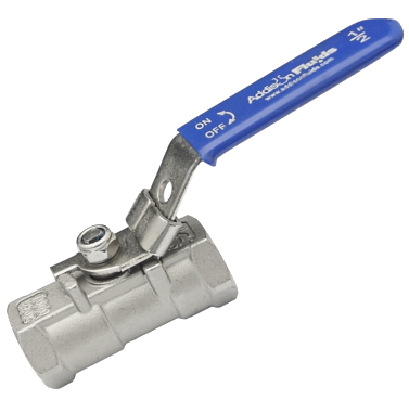
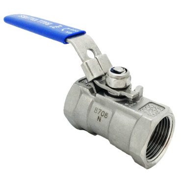
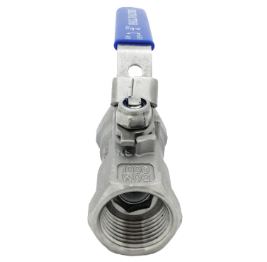
All photographs of the stocked item, not renders. Tap a thumbnail above to change the view.
No body joint anywhere. Body and both end connections are a single piece of SS316. Compare this with the two-piece, where a seam runs across the body behind the hex.
The reduced bore is visible. The hole through the ball is plainly smaller than the thread around it — the trim went in through this end during manufacture, and that is what limits the bore.
Across the body means shut. Ninety degrees is the whole travel, and the handle position tells an operator the state of the line from across the room.
The stem assembly. Stem nut, spring washer and packing gland stacked on the stem — items 10 to 13 on the parts list. This is the only part of the valve that can be adjusted in service.
Everything that goes on a purchase order.
| Item | Detail |
|---|---|
| Size range | 1/4″ to 4″ (DN8 to DN100) |
| Body construction | One piece — body and end connections from a single piece of material. Not serviceable |
| Bore | Reduced bore, always — it is set by the construction |
| Body material | Stainless steel SS316, with CF8M where the part is cast |
| Working pressure | 1000 PSI cold — 63 bar on the manufacturer’s curve, derating with temperature |
| Working temperature | −29 °C to 150 °C — 150 °C is a hard ceiling |
| Connection type | Threaded BSPP or NPT |
| Seat and seals | PTFE seat, seal gasket, stem seal and stem packing |
| Ball and stem | SS316, with an SS304 anti-static device |
| Operation | Quarter turn manual lever |
| IMPA codes | 75 24 11 to 75 24 18 (1/4″ to 2″, BSPP) |
| Stock | Singapore and Malaysia warehouses — out within 24 hours |
| Size | Bore | L (mm) | H (mm) | Handle E (mm) | Weight | Part no. BSPP | Part no. NPT | IMPA BSPP |
|---|---|---|---|---|---|---|---|---|
| 1/4″ | 5 | 40 | 24 | 72 | 0.07 kg | VL-S-B1-G-1000-04 | VL-S-B1-N-1000-04 | 75 24 11 |
| 3/8″ | 7 | 45 | 27 | 80 | 0.10 kg | VL-S-B1-G-1000-06 | VL-S-B1-N-1000-06 | 75 24 12 |
| 1/2″ | 9 | 57 | 34.5 | 97 | 0.20 kg | VL-S-B1-G-1000-08 | VL-S-B1-N-1000-08 | 75 24 13 |
| 3/4″ | 12 | 60 | 40 | 92 | 0.26 kg | VL-S-B1-G-1000-12 | VL-S-B1-N-1000-12 | 75 24 14 |
| 1″ | 15 | 70.5 | 44 | 125 | 0.40 kg | VL-S-B1-G-1000-16 | VL-S-B1-N-1000-16 | 75 24 15 |
| 1¼″ | 20 | 78 | 50 | 125 | 0.70 kg | VL-S-B1-G-1000-20 | VL-S-B1-N-1000-20 | 75 24 16 |
| 1½″ | 25 | 83.5 | 54 | 155 | 0.80 kg | VL-S-B1-G-1000-24 | VL-S-B1-N-1000-24 | 75 24 17 |
| 2″ | 32 | 99.5 | 60 | 155 | 1.28 kg | VL-S-B1-G-1000-32 | VL-S-B1-N-1000-32 | 75 24 18 |
| 2½″ | 38 | 122 | 87 | 183 | 2.34 kg | VL-S-B1-G-1000-40 | VL-S-B1-N-1000-40 | — |
| 3″ | 50 | 148.5 | 97 | 183 | 3.50 kg | VL-S-B1-G-1000-48 | VL-S-B1-N-1000-48 | — |
| 4″ | 65 | 193 | 117 | 220 | 9.05 kg | VL-S-B1-G-1000-64 | VL-S-B1-N-1000-64 | — |
Note the handle column E: at 4″ the lever is 220 mm and has to sweep a quarter circle — check the space before ordering. And note the jump in weight: from 3.50 kg at 3″ to 9.05 kg at 4″. IMPA codes run to 2″; the larger sizes do not carry one.
Every bore, length, height, handle and weight matches across the two thread forms — so the only thing that changes is the part number. We verified that row by row rather than assuming it.
They will start to engage and feel tight, then leak. If you are not certain which is on the existing pipework, send a photo before ordering.
A 1″ valve has a 15 mm bore — the same as a 1/2″ full-bore valve. Size on flow, not on the thread.
75 24 11 through 75 24 18 cover 1/4″ to 2″ in BSPP; above that, and for NPT, order by part number.
4″ is 9.05 kg against 1.28 kg at 2″ — worth knowing before it is specified for an overhead or unsupported position.
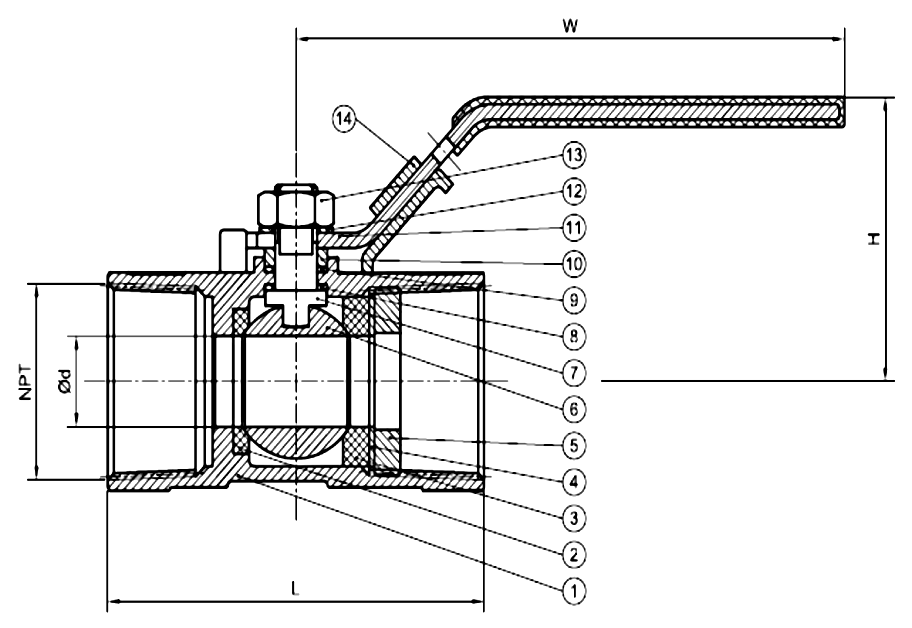
The callout numbers on this drawing match the numbers in the bill of materials below — and the dimension letters (L length, H height, d bore diameter) match the columns in the dimension table above.
The section is the quickest way to see why the bore is reduced: the ball, seats and stem all had to pass in through one end connection, so the ball cannot be over-sized.
Items 1 to 13 match, but the drawing marks a 14th item on the handle that the published table does not name. We have not guessed at it — ask us and we will confirm with the factory before you order spares.
Same dimension, different letter — the manufacturer is not consistent between the drawing and the table. Use the E column in the size table for the figure, and check it against your swing clearance.
| No. | Part name | Material |
|---|---|---|
| 1 | Body | SS316 and CF8M |
| 2 | Cap | SS316 |
| 3 | Seat | PTFE |
| 4 | Ball | SS316 |
| 5 | Seal gasket | PTFE |
| 6 | Stem seal | PTFE |
| 7 | Stem | SS316 |
| 8 | Anti-static device | SS304 |
| 9 | Stem packing | PTFE |
| 10 | Packing gland | SS304 |
| 11 | Spring washer | SS301 |
| 12 | Handle | SS201 |
| 13 | Stem nut | SS304 |
Body, cap, ball and stem in SS316; seat, seal gasket, stem seal and stem packing in PTFE. If you need to know what touches your fluid, that is the whole list.
It is the correct specification for a cast valve body and is chemically equivalent to wrought 316.
A ball turning on PTFE seats is electrically isolated from the body; the SS304 anti-static device (item 8) bonds the ball and stem back to the body so charge cannot build up. It is standard here, not an option.
Lower grades than the body, on parts outside the pressure boundary — normal practice, and worth knowing if the valve lives somewhere salty.
| Temperature | Pressure (bar) | Pressure (PSI) | % cold rating |
|---|---|---|---|
| −30…+20 °C | 63 | 914 | 100% |
| 40 °C | 59.8 | 867 | 95% |
| 60 °C | 56.5 | 819 | 90% |
| 80 °C | 53.3 | 773 | 85% |
| 100 °C | 50.1 | 727 | 80% |
| 120 °C | 46.8 | 679 | 74% |
| 140 °C | 43.6 | 632 | 69% |
| 150 °C | 42 | 609 | 67% |
The operating range is −29 to 150 °C, and the limit is set by the PTFE seat, not the SS316 body. At 150 °C the valve holds only two thirds of its cold rating — state pressure and temperature together when ordering.
63 bar cold, 42 bar hot — 67%. If you sized on the catalogue figure and the line runs warm, the margin you thought you had is not there.
The curve is flat from −30 °C, so ambient and chilled service get the full rating. Derating only begins once the line is warm.
The curve drops vertically to zero there. Do not design a small margin beyond it.
Rated 1000 PSI, with the derating curve drawn to 63 bar. For duty near the limit, give us the pressure and temperature together and we confirm against the specific part number.
It is the PTFE seat that governs, and the two-piece and three-piece use the same seat material.
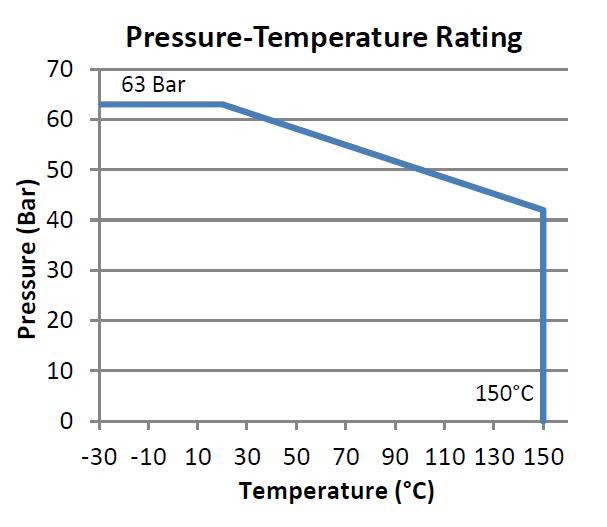
The curve is flat to about +20 °C, then falls in a straight line to 42 bar at 150 °C — and stops there.
Eight variants. Two questions separate them: do you need full bore, and does the valve have to open.
All eight, side by side: the comparison table. And if the line cannot be shut down for maintenance, skip the one- and two-piece — take the three-piece, whose centre section lifts out while the end caps stay in the pipe.
Dimensions and part numbers are in the catalogue, as printed; stock and price are not — send the list and we confirm both.
A ball valve whose body and end connections are made from a single piece of material. The solid, cast body significantly decreases the risk of leakage because there is no body joint. The trim and seals are inserted through one of the end connections, which is why the port size cannot equal the line size and the valve is always reduced bore. The sectional drawing on this page shows exactly why.
Always reduced bore. It is a consequence of the construction, not an option — the trim has to pass through an end connection, so the ball cannot be over-sized. At 1/2″ the bore is 9 mm against 15 mm for a full-bore valve, which is about 36% of the flow area. If you need full bore, use the two-piece or three-piece.
No. There is no way into the body, so it cannot be disassembled — when the PTFE seat wears, the valve is replaced. That is the deliberate trade for having no body joint. If seat replacement is foreseeable, specify the two-piece; if it must happen without stopping the line, the three-piece.
When leak-tightness matters more than flow and nobody will ever open the valve. The one-piece has the fewest leak paths and is the cheapest of the three. Choose the two-piece instead if you need full bore, if you may want to replace internal parts, or if you need 2000 PSI — which only the two-piece offers.
63 bar at ambient, derating to about 42 bar at 150 °C — two thirds of the cold figure. The valve is dead at 150 °C. The limiting part is the PTFE seat, not the stainless body. For duty near the limit, give us the pressure and temperature together and we confirm against the specific part number. The full table and the graph are on this page.
Yes — a sectional drawing is on this page, with numbered callouts that match the bill of materials and the dimensions L, H, W and the bore Ød marked. Two things to know: the drawing shows a 14th callout that the published parts table does not name, and it labels the handle span W where the size table calls it E.
SS316 body, cap, ball and stem (CF8M where cast); PTFE seat, seal gasket, stem seal and stem packing; an SS304 anti-static device and packing gland; SS301 spring washer; SS201 handle. The full numbered list, and the drawing it maps to, are on this page.
Both, and they are dimensionally identical — every bore, length, height, handle length and weight matches across the two thread forms, so only the part number changes. They are not interchangeable with each other, though: a mismatched pair engages and feels tight, then leaks.
1/4″ to 4″ (DN8 to DN100) in both BSPP and NPT — eleven sizes, bores from 5 mm to 65 mm, weights from 0.07 to 9.05 kg. Send the size and thread form and we will confirm availability and a landed price. The full dimension table is above.
We hold it in our Singapore and Malaysia warehouses, out within 24 hours of your PO, with quotes within 2 working hours.
Related: all ball valves · class 150 threaded fittings for the pipework.